Overview
This project focused on modeling, simulating, and developing locomotion gaits for a soft-robotic module based on Handed Shearing Auxetic (HSA) actuators. The primary goal was to reproduce the physical module’s behavior in simulation, and then apply learning-based methods to discover novel and unintuitive gaits. The project consisted of three phases:
- Modeling a physics-informed approximation of the HSA actuators to capture their deformation and actuation behavior in simulation.
- Replicating existing gaits observed on the physical robot to validate that the simulated system reflected real-world dynamics.
- Training the robot across various terrains, using reinforcement learning - enabling the emergence of new and unintuitive locomotion strategies.
System Modeling
Handed Shearing Auxetic (HSA)
Handed Shearing Auxetic (HSA) actuators are soft, flexible structures that change shape in unusual ways when they are twisted or compressed. They can stretch, twist, and deform smoothly based on their internal pattern.
Each structure can be either left-handed or right-handed, which means it naturally twists in a different direction when it moves. By combining these opposite twists in a unit, we can create a variety of movement patterns and behaviors.
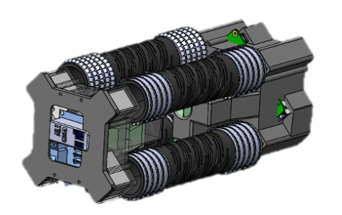
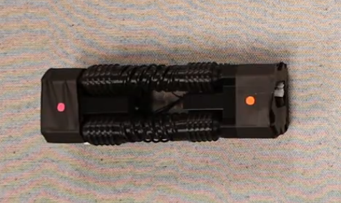
The Robotic Matter Lab at Northwestern University has been developing a robot out of this structural arrangement. Specifically, four HSA modules with pairwise opposite handedness are combined, with continous rotation servo motors attached at each end. The resulting robot is shown in the images below.
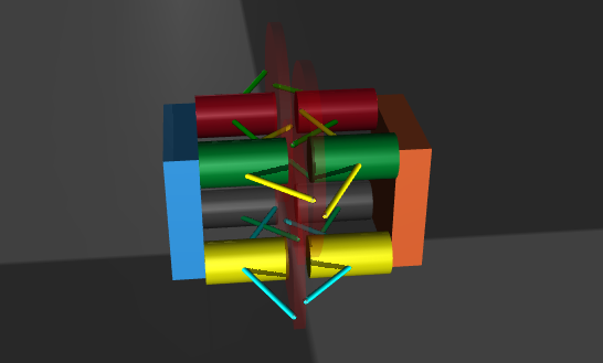
Simulation Model
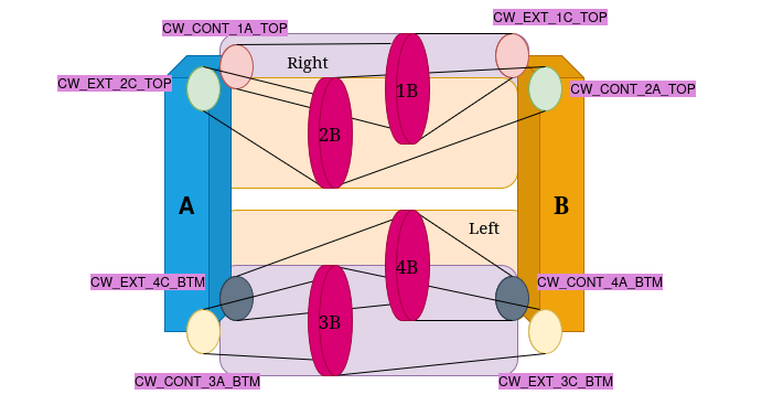
The next challenge was to develop an approximation of the HSA structure that could reproduce its key behaviors while remaining simple enough for the MuJoCo physics engine to handle contact and dynamics efficiently. After several iterations, I settled on a representation built from an arrangement of cylinders and tendons in MuJoCo. This structure converts rotational motion at one end into axial extension or contraction through a central disc. The main tunable parameters were the tendon stiffness and the radius of the central disc. My target was to match the real HSA module’s extension of approximately 6 cm; the final model achieved extensions in the range of 4–4.5 cm.
The extension and contraction of the mechanism is controlled by the position servo motors in MuJoCo. They are made continous by setting their range to be -1000 \(\pi\) to +1000 \(\pi\). An example of contraction and extension can be seen below.
Replication of Standard Gaits
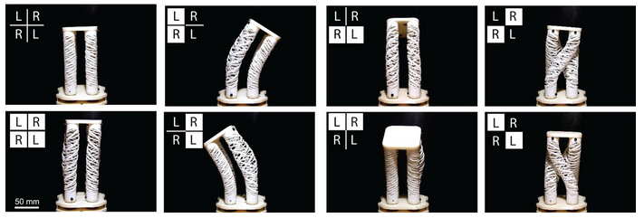
To validate the simulated model against the real system, the next goal was to replicate the existing gaits observed in the physical robot. To achieve this, I developed a control API around MuJoCo that allowed me to directly command specific gaits in simulation. I also added functionality for initializing and closing the simulation, modifying contact parameters, and retrieving the robot’s state. The gaits I was able to reproduce reliably included:
Extension & Contraction: In both demos, one block is constrained in place while the other is free to expand and contract according to the commanded motor inputs.
Bending: Bending enables the robot to extend sideways and is particularly useful for in-place rotation. However, fully capturing its capability in simulation remains challenging. Both demonstrations are sped up 2×.
Crawling: Crawling is achieved through rapid cycles of extension and contraction. On the physical robot, specially designed fins provide anisotropic friction along a single axis, with different coefficients in the positive and negative directions, enabling an inchworm-style motion. However, MuJoCo does not natively support anisotropic friction along a single axis. To address this, I implemented a stateful workaround that dynamically adjusts the friction coefficient based on the robot’s direction of travel. Below are demonstrations of the crawling mode in both simulation and on the real robot, with both videos sped up 2×.

The physical robot was also capable of a twisting gait; however, despite extensive tuning, this mode could not be reproduced in my simulation due to inherent limitations in the structural approximation. The intention was then for the reinforcement learning phase to uncover alternative gaits that could provide similar advantages. With this in mind, I moved into the training phase.
Reinforcement Learning for Locomotion
Environment Design
For the reinforcement learning pipeline, I chose to use the Stable-Baselines3 library and spent time studying its MuJoCo examples to understand the expected structure and workflow. For the training policy, I used Proximal Policy Optimization (PPO) algorithm for its reliability and effectiveness in continous action spaces.
I then implemented two custom Python classes. The first was a MuJoCo base class that wrapped the core MuJoCo API, providing methods to initialize, step through, and close the MuJoCo simulation. It also exposed additional functionality such as accessing the current system state, measuring contact forces, and updating the pose of static markers in the environment.
The second class extended this base to include all reinforcement-learning–specific components, including computing rewards and penalties, constructing observations, updating the info dictionary, and advancing the environment by one RL timestep.
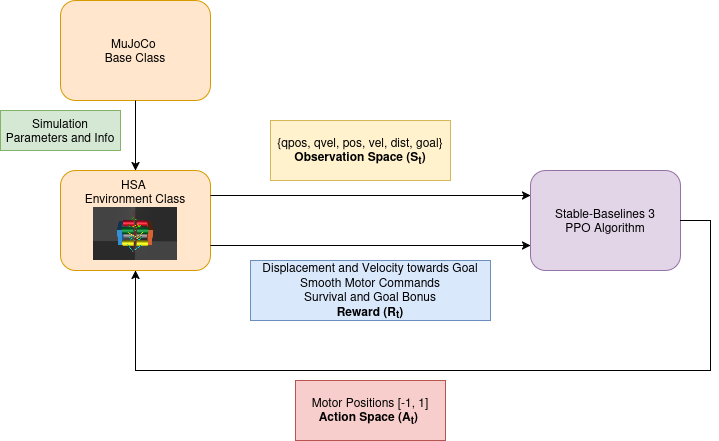
The final observation space and action space for my model looked like this:
Observation Space = {
  "Motor Positions": 8 values (np.float32),
  "Motor Velocities: 8 values (np.float32),
  "COM Position": 2 values (x, y),
  "COM Velocity": 3 values (v_x, v_y, v_z),
  "Distance To Goal": 1 value (float32),
  "Vector To Goal": 2 values (n_x, n_y)
}

Action Space = spaces.Box(low=-1.0, high=+1.0, shape=8, dtype=np.float32)
An important design choice was to use position control in the reinforcement learning environment. Initially, the action space consisted of direct position setpoints for each motor, while the required torques were handled internally by MuJoCo’s built-in PD controller. In the final environment, I instead used position increments as the action output. This change was necessary because the position limits were removed, allowing the motors to behave as continuous-rotation servos.
The action space is normalized such that a value of +1.0 corresponds to an increase of 0.1785 radians (approximately 10°), while −1.0 corresponds to a decrease of the same amount. All actions are scaled by 0.1785 radians and applied as increments to the current motor positions.
Reward Function Design
A significant portion of my reinforcement learning work involved designing the reward functions and tuning their weights. This step was critical, as both the success and stability of training depend heavily on the structure of the reward. In the initial versions, I rewarded forward velocity while penalizing excessive contact forces and overly large actions.
Initial Reward Design
| Parameter | Value | Description |
|---|---|---|
forward_reward_weight | 1.0 | Rewards velocity in any direction |
ctrl_cost_weight | 0.01 | Penalizes large control inputs |
contact_cost_weight | 0.00005 | Penalizes large contact forces |
In the absence of a specific goal position, the robot learned to explore its environment and ultimately discovered a rolling locomotion mode. This behavior is also one of the standard gaits of the physical robot.
However, it became clear that rewarding velocity alone would not encourage the discovery of new gaits. To address this, I introduced a goal position marker into the environment, which was also reflected in the observation space. This gave the robot a concrete target to move toward, requiring a shift in the reward design - from simply encouraging speed to promoting progress toward the goal.
I introduced a distance-based reward to encourage movement toward the goal position. Joint velocities and accelerations were penalized to prevent excessive or unstable motion. I also enforced a mechanical constraint between the motors to preserve the handedness pattern of the HSA modules, which was otherwise disrupted by allowing continuous motor rotation.
Additionally, a small survival bonus was granted at each timestep, while an early-termination penalty was applied if an episode ended prematurely. This penalty was skipped if the robot reached the goal, in which case a large positive reward was issued to reinforce the desired behavior.
Final Reward Design
| Parameter | Value | Description |
|---|---|---|
distance_reward_weight | 10.0 | Rewards movement towards goal |
forward_reward_weight | 6.0 | Encourages velocity towards goal |
ctrl_cost_weight | 0.001 | Penalizes large control inputs |
acc_cost_weight | 0.00001 | Penalizes large joint accelerations |
joint_vel_cost_weight | 0.0005 | Penalizes large joint velocities |
constraint_cost_weight | 0.05 | Enforces handedness based motor coupling |
alive_bonus | 0.03 | Survival bonus |
early_termination_penalty | 0.1 | Penalizes premature episode termination |
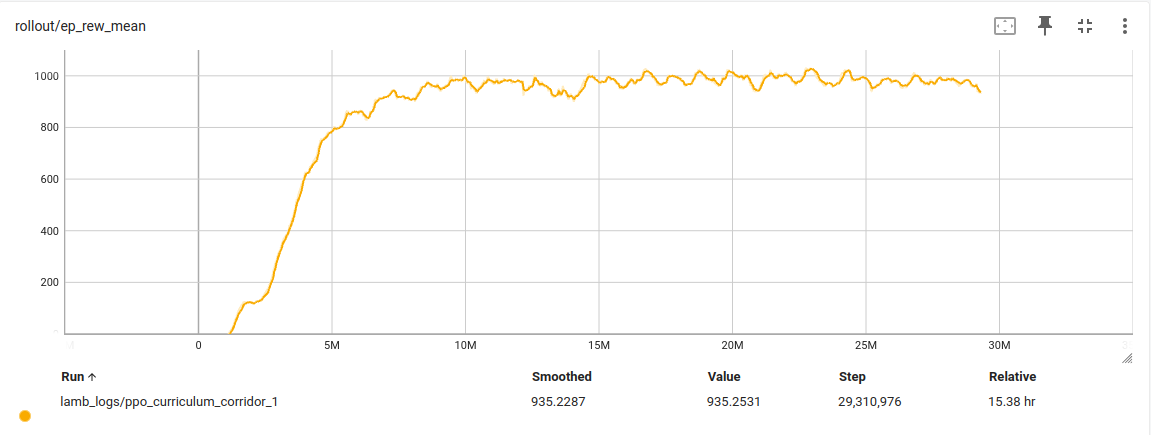
With these weights I trained on two different terrains, a flat ground and a corridor. The reward plots are shown, and the evalutation videos are in the next section.
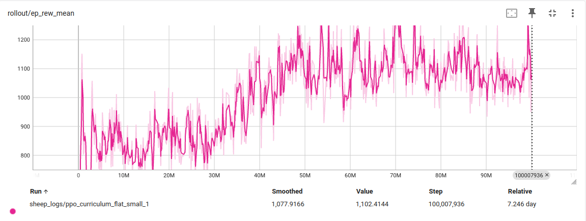
Results
I began training on flat terrain, tasking the robot with navigating to a goal position. I implemented a curriculum that gradually increased the goal distance over time. Initially, goals were sampled within a 2.0 m radius. Once the robot achieved a success rate above 75%, this range was expanded to 2.3 m, and continued increasing until it reached the 4.5 m bounds of the simulated environment. After 60 M timesteps, the robot was able to reach targets up to 4.2 m away. Some successful runs are shown below.
Another notable result emerged in the corridor terrain, where the robot was tasked with moving along a narrow passage. Using only a single HSA unit, the robot exhibited a distinctive wiggling motion. Because this mode of locomotion is relatively slow, the goal position was placed close to the robot.
Future Work
With more time, I would like to add the following functionalities to this project:
- Support anisotropic friction
- Incorporate directional friction directly into the model, rather than adjusting it dynamically, to enable state-independent behavior.
- Build a Sim2Real pipeline
- Deploy the trained policies on the physical robot to transfer simulation results to the real world.
Acknowledgements
This project is part of my Master of Science in Robotics at Northwestern University. Thank you to Prof. Ryan Truby, Prof. Matthew Elwin, and Dr. Taekyoung Kim for their valuable guidance and support throughout their project. I also thank An Nguyen for her thought-provoking contributions.