Demo Video
This project involved modeling a Jack and a Box and the impacts between them using Lagrangian Mechanics.
Frames and Transformations
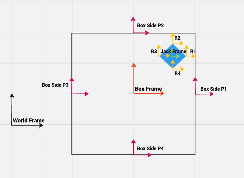
The image below depicts the frames used for modeling the dynamics of the system. There are in total 11 frames, the World frame, the Box frame at the box’s geometrical center and the Jack frame at the jack’s geometrical center. To accurately check for impacts, there are 8 additional frames, 4 for each corner of the Jack, labelled r1 through r4 and 4 for each side of the box (located at the center of each side), labelled p1 through p4.

The configuration of the system is represented using 6 configuration variables xBox, yBox, thBox, xJack, yJack, thJack. The variables xBox, yBox, thBox represent the pose of the box with respect to the World frame and the variables xJack, yJack, thJack represent the pose of the jack with respect to the Box frame. The configuration variables are stored as vector q
Euler Lagrange Equations
To solve the Euler Lagrange equations, we first construct the inertia matrices of the box and the jack. Further, to calculate the Lagrangian L, the kinetic energy of the system is calculated using the inertia matrix and the body velocities - obtained by using the inverse, derivative and unhat operations on the box and jack transformation matrices in the World frame. The potential energy is calculated by multiplying the y-coordinate of the box and jack in the World frame, with mass and gravity. Once, we obtain both the kinetic and potential energy, the Lagrangian is simply the subtraction of those terms.
The Euler Lagrange equations, in terms of the Lagrangian L and configuration variables q are:
$$ \frac{d}{dt} \left( \frac{\partial L}{\partial \dot{q}} \right)- \frac{\partial L}{\partial q} = F_{ext}$$
where \(F_{ext}\) refers to the external force applied to reduce the downward motion of the box.
Constraints and Impacts
In order to simulate the impact of the jack with the box, we need to add constraints to check when the impact occurs, Since we are checking for impacts between the 4 sides of the box and the 4 corners of the jack, we have 16 impact constraints that are added. As an example, the constraint to check if the r1 corner of the jack collided with the p1 side of the box is to check if the x coordinate of the r1 corner is equal to the x coordinate of the p1 side of the box. In code, this is done by a function, which checks if this condition is within a small threshold ~0.1, and returns True if that is the case.
To correctly simulate the system, it is required to calculate the post impact velocities of the jack and the box. This is done by solving the impact equations for the velocities, and the constant \(\lambda\), which is multiplied with the derivative of the constraints. After solving, the impact equations return more than 1 solution, but only the one which has postive non zero \(\lambda\) is chosen. This is because the box acts as a surface pushing the jack away and any \(\lambda\) which is less than zero (or also equal to zero), will allow the jack to pass through the box which is not desirable.