Demo Video
This project involved generating a trajectory for the end effector of the the YouBot mobile manipulator, performing odometry to keep track of the chassis as it moved, and perform feedback control to drive the robot to pick and place a block at a desired location.
Overview
This project was divided into 3 major milestones:
- Milestone1 : Reference Trajectory Generation
- Milestone2 : youBot Kinematics Simulator
- Milestone3 : Feedforward Control
Each of these milestones were implemented in separate python files, with their outputs verified against the test outputs provided. Finally, all of them were integrated into one main loop which generated a csv file, consisting of multiple lines, each with 13 comma-separated values:
chassis phi, chassis x, chassis y, J1, J2, J3, J4, J5, W1, W2, W3, W4, gripper state
where chassis phi, chassis x and chassis x represent the chassis’ position and orientation, J1 to J5 represent the arm joint angles, W1 to W4 represent the wheel joint angles, and gripper state represents the state of the gripper - open or closed.
There are functions from the modern-robotics library used in this project.
Reference Trajectory Generation
The trajectory of the end effector is generated in 8 different segments as a Cubic Via Point Trajectory. The 8 segments of the trajectory comprise of:
- A trajectory to move the gripper from its initial configuration to a “standoff” configuration above the block.
- A trajectory to move the gripper down to the grasp position.
- Closing of the gripper.
- A trajectory to move the gripper back up to the “standoff” configuration.
- A trajectory to move the gripper to a “standoff” configuration above the final configuration.
- A trajectory to move the gripper to the final configuration of the object.
- Opening of the gripper.
- A trajectory to move the gripper back to the “standoff” configuration
For some segments, the code uses the CartesianTrajectory function and for others the ScrewTrajectory function. Both of these functions are found in the modern robotics library.
youBot Kinematics Simulator
The kinematics of the YouBot is simulated using a function which takes in the current configuration of the robot - position, wheel and joint angles, the wheel and arm joint speeds and outputs the next configuration of the robot using first order Euler step and odometry.
The transformation matrix from the fixed frame to the base frame of the youBot’s chassis is given by
$$
T_{sb}(x, y, \phi) = \begin{pmatrix}
\cos(\phi) & -\sin(\phi) & 0 & x \\
\sin(\phi) & \cos(\phi) & 0 & y \\
0 & 0 & 1 & 0.0963 \\
0 & 0 & 0 & 1
\end{pmatrix}
$$
where, x, y and phi are used to represent the chassis’ position and orientation.
The base frame of the arm is at a fixed offset from the base frame of the chassis. All these transformation matrices are specified in a params file.
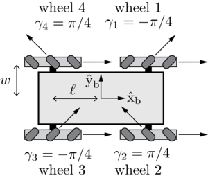
The odometry of the chassis is calculated for the the youBot using odometry equations specified in section 13.4 of the Modern Robotics textbook, which use these parameters. The radius of each wheel r is 0.0475 m, the forward-backward distance between the wheels 2l is 0.47 m, and the side-to-side distance between the wheels 2w is 0.3 m.

Feedforward Control
After obtaining the reference trajectory and the kinematic simulator for the youBot, the function FeedbackControl was used to calculate the kinematic task-space feedforward plus feedback control law:
$$ V(t) = [Ad_{X^{-1}Xd}]V_{d}(t) + K_{p}X_{err}(t) + K_{i} \int_0^t X_{err}(t)dt $$
where:
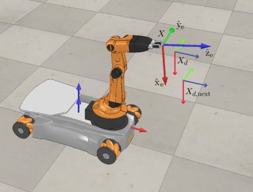
\(X\) is the current actual end effector configuration
\(X_d\) is the reference end effector configuration, \(X_{err} = \log(X^{-1}X_{d})\)
\(X_{d,next}\) is the reference end effector configuration at the next time step
and so, \([V_d] = (1/\Delta{t})\log(X_{d^{-1}}X_{d,next})\) gives us the commanded end-effector twist \(V\) at every time step.

To turn the end-effector twist into commanded wheel and arm joint speeds, we use the pseudo-inverse of the mobile manipulator Jacobian \(J_e(\theta)\).