The goal of this project was to design and program a low-level brushed DC motor controller using a PIC32MX170F256B microcontroller, capable of precise position control. This system was built from the ground up, combining real-time embedded programming, UART and I2C communication, and a multi-loop control structure for closed-loop motor control.
Hardware Setup
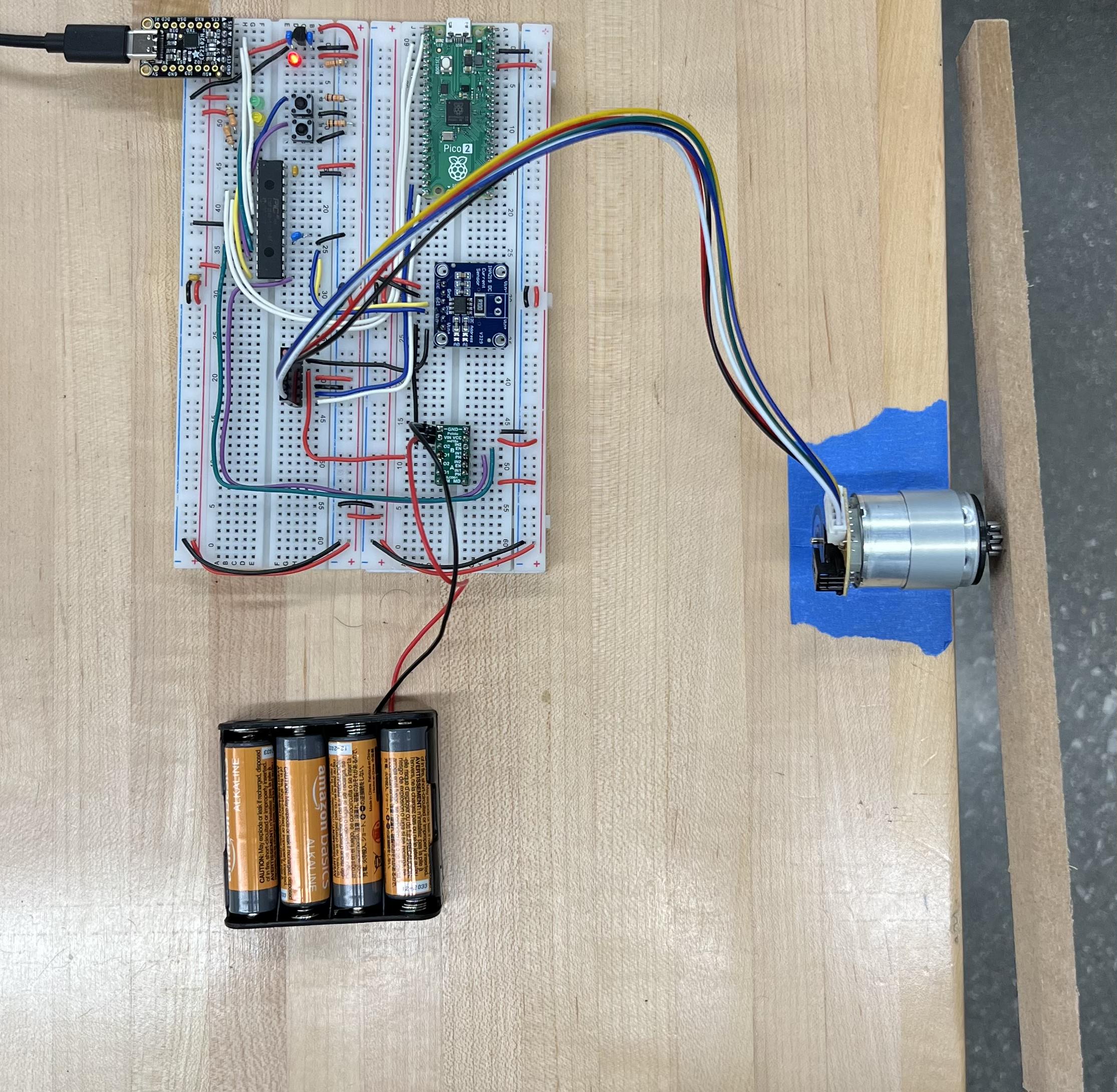
The current hardware setup for the motor controller system includes the following components:
- PIC32MX170F256B Microcontroller : Serves as the core controller with UART communication, control loops & PWM signal generation
- Raspberry Pi Pico 2 : Reads encoder pulses and transmits position data to PIC32
- CP2102N USB-to-Serial Converter : Enables UART-based programming and terminal communication between the PIC32 and a host computer
- INA219 Current Sensor : Monitors motor current via I2C for closed-loop current control
- DRV8835 Dual H-Bridge Driver: Drives the brushed DC motor using PWM and direction signals from the PIC32
- Brushed DC Motor with Load Beam : Mechanical actuator used for position tracking and load testing
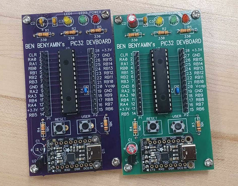
The PIC32, CP2102N, and supporting components such as capacitors, resistors, switches, and LEDs were neatly integrated into a custom PCB designed by my cohort mate - Ben Benyamin.
Firmware and Interface
The programming involved two components: firmware for the PIC32, written in C, and a Python-based interface running on the host computer.
PIC32 Firmware
Two main control loops were implemented via timer-driven interrupts:
- Current Control ISR (5 kHz) : Implements a PI controller for maintaining target motor current
- Position Control ISR (200 Hz) : Implements a PID controller for tracking desired position trajectories
The PWM signal for driving the motor is generated using the Output Compare module at a frequency of 20 kHz. In the main program loop, a UART-based command parser listens for instructions from the Python terminal interface and executes commands such as setting control gains, loading trajectories, and enabling/disabling control modes.
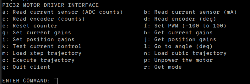
Python Interface
A terminal-based interface was built using pyserial to allow real-time communication with the motor controller. Users can input commands to tune gains, send reference trajectories, and view sensor data streamed from the PIC32 over UART.
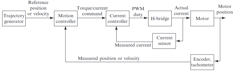
Control System
The control strategy followed a cascaded approach, tuning the inner current control loop, followed by the outer position loop.
Current Control
To tune the current loop, a 100 Hz square wave reference alternating between ±200 mA was used. After adjusting the proportional and integral gains, a stable and responsive current tracking was achieved.
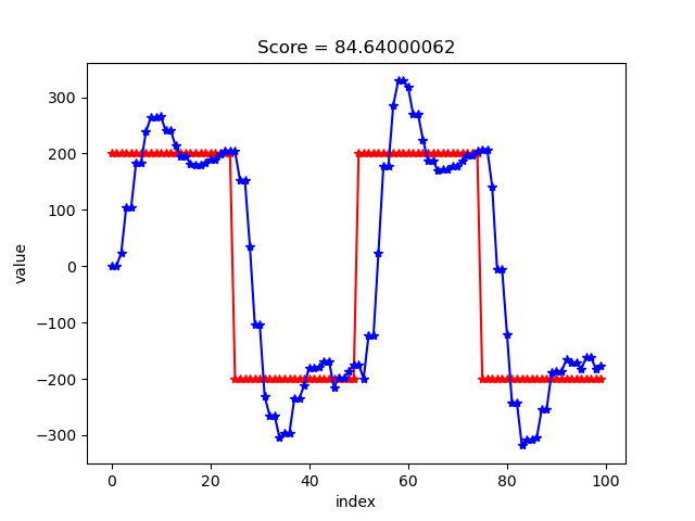
Gains: Kp = 0.03 Ki = 0.05
Position Control
With current control stabilized, the position controller was tuned using both step and cubic spline trajectories. Gains were selected to ensure smooth tracking without overshoot or instability.
Step Trajectory
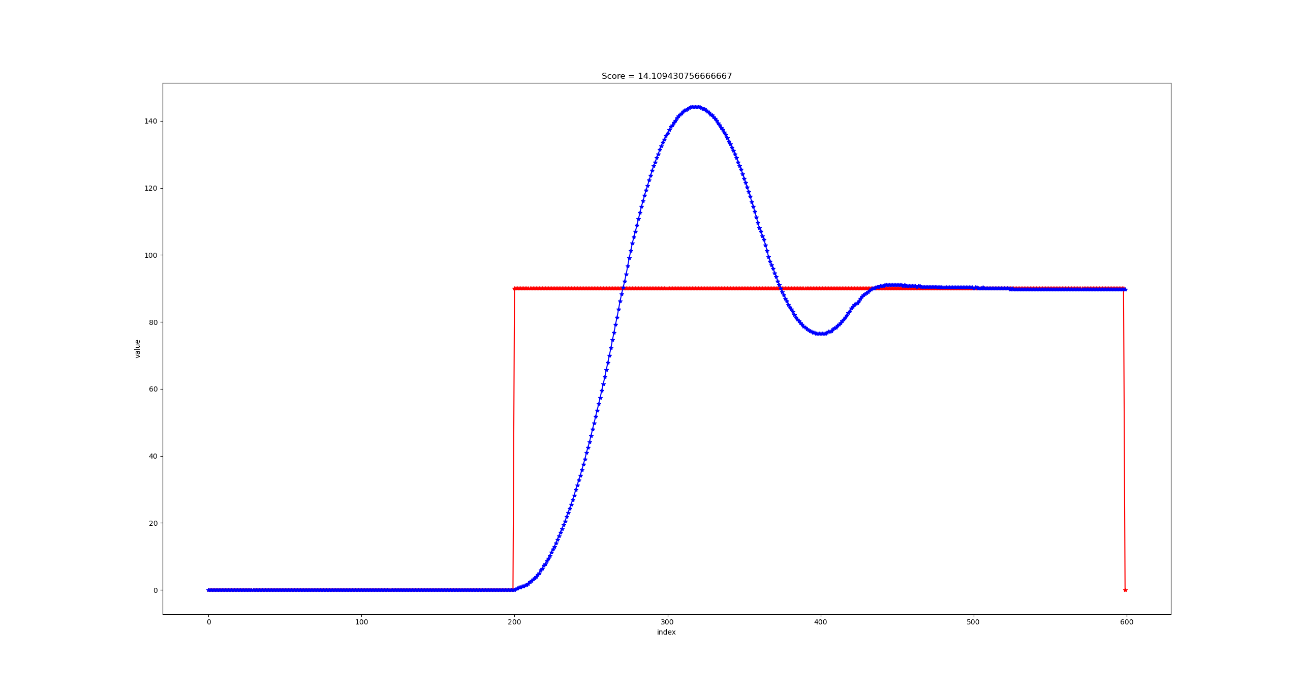
Gains: Kp = 8 Ki = 0.01 Kd = 1500
Cubic Trajectory
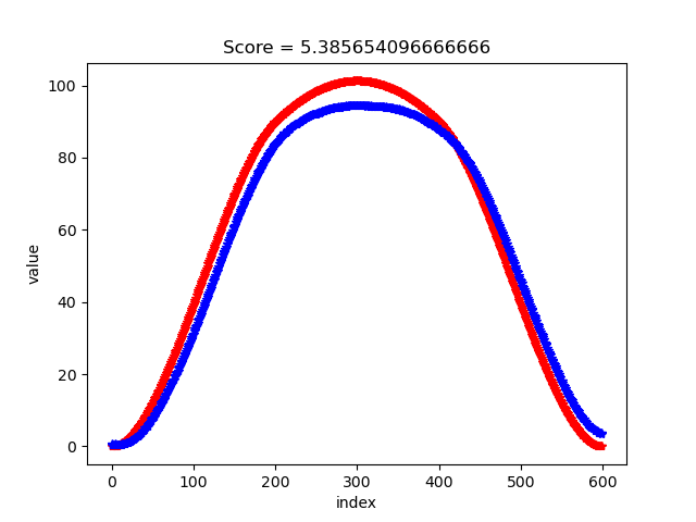
Gains: Kp = 8 Ki = 0.01 Kd = 1500