Paper Byte is an ESP32-based e-reader that parses and renders EPUB-style ebooks, with simple three-button navigation.
Hardware Setup
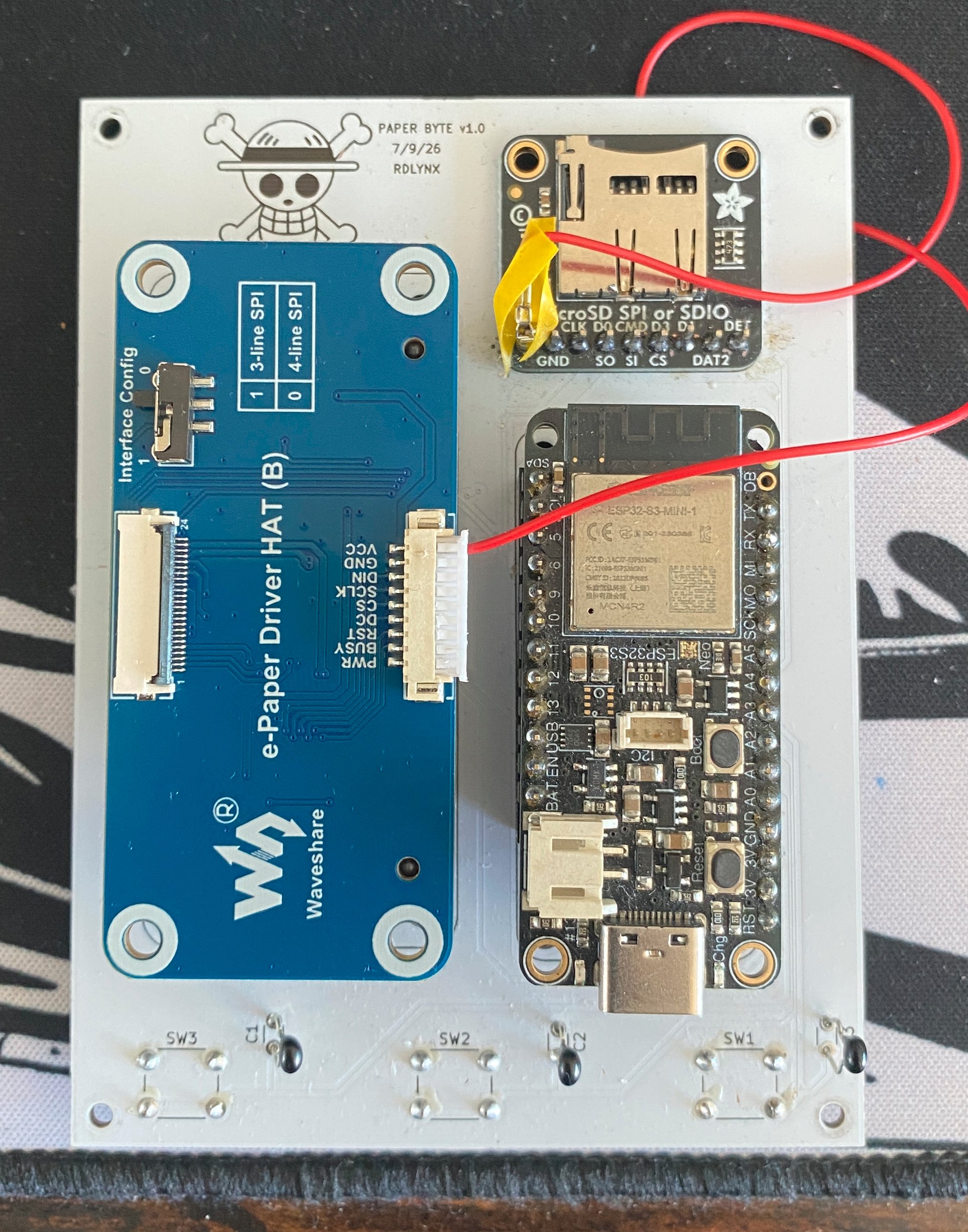
The hardware setup includes the following components:
- Adafruit ESP32-S3 Feather: The main board, responsible for parsing EPUB files stored on the SD card and driving the e-ink display over SPI
- Adafruit SD Card Module: Provides SD card access over SPI, including a card-detect pin for hot-swapping
- Waveshare 5-inch E-Paper Display: Renders the parsed EPUB content for reading
- E-Paper Display Driver HAT: Communicates with the display over SPI to push rendered frames
- Tactile Switches: Handles navigation — previous page, next page, and menu select
Concept and Design
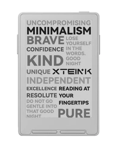
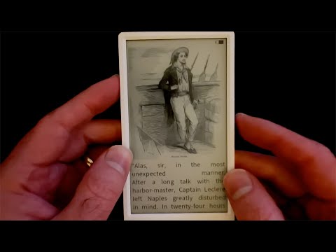
Paper-Byte emerged from my love of reading. I kept finding myself reading books on my phone, which was not doing my eyes any favors. I considered buying an XTEink e-reader, but where’s the fun in buying something when I could spend twice the money building it myself? A quick search on YouTube turned up only one guide for building one, and it used a not-so-great e-ink screen. So I set out to build my own. The YouTube guide by atomic14 was a huge help in understanding how to parse EPUB files, and of course Claude was instrumental in helping me implement it.
My initial attempt was to use a Raspberry Pi Zero 2W instead of an ESP32. There were two main reasons for this: I had a Pi Zero 2W readily available, and I believed it would be much easier to write firmware for something running Linux with a built-in SD card slot, rather than something with the limited RAM and storage of an ESP32. But I ran into several challenges along the way. The Pi had no way to sense the state of charge of its battery, so I had to add an INA219 current sensor to estimate it. It also needed a 5V supply, which meant adding a boost converter to step up the voltage from the 1S LiPo battery. On top of that, the Pi drew a much higher standby current than the ESP32, so I had to add a power switch to cut that drain. And finally, I needed a TP4056 charging module to charge the battery over USB-C. I managed to source all these parts, wire them together, and get the firmware running — but the mechanical design was a different beast entirely. Fitting everything together turned out clunky, and the parts never quite sat right.
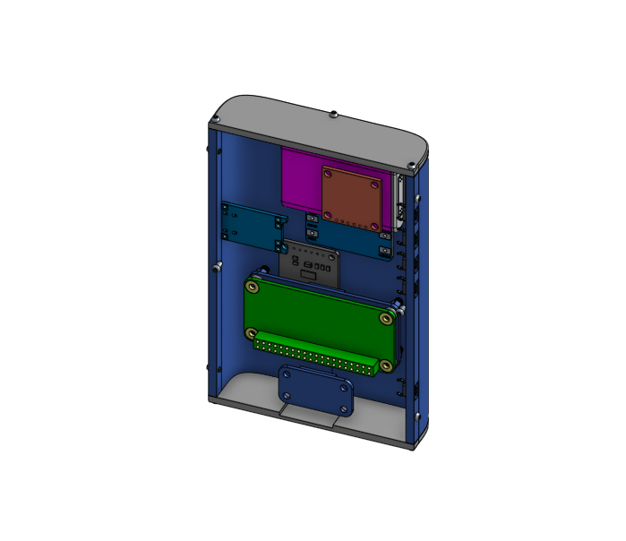
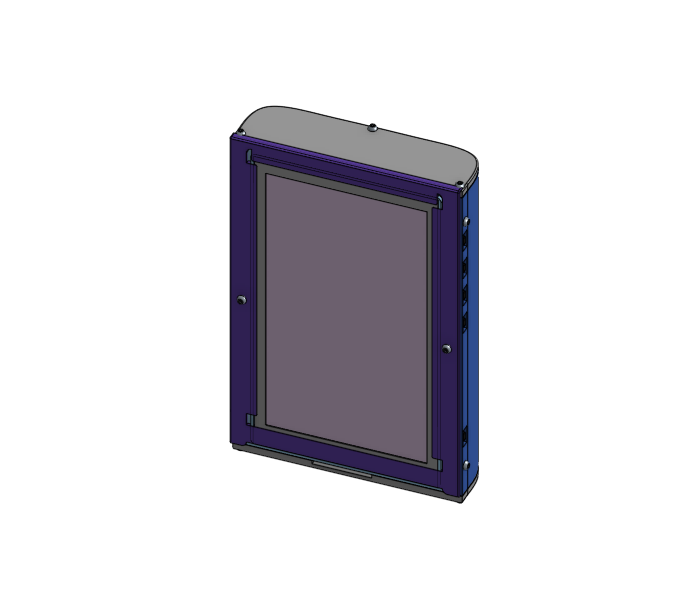
To make matters worse, my design didn’t account for the space the wiring would take up, so once everything was soldered together, the case had to grow even clunkier to fit it all. I ended up settling for a desk-stand-style design, which wasn’t exactly easy on the eyes.
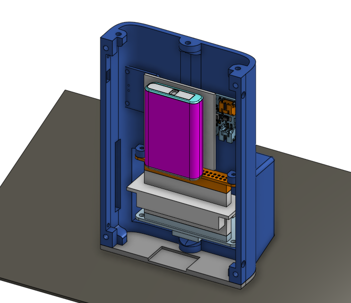
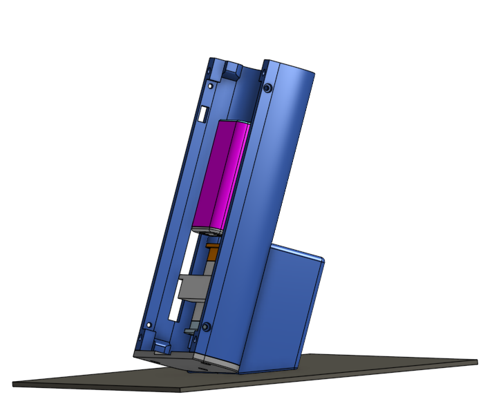
After more research, I found the Adafruit ESP32-S3 Feather, which has a MAX1708 charging module built in — letting me read the battery’s state of charge directly over I2C — and a USB-C port that could charge any battery connected to the board. It also draws a much lower standby current, so the power switch became unnecessary too. In one move, I eliminated three components; the only thing I still needed to add was an SD card module for storage, with the ESP32 reading books over SPI. I’d found the perfect board for the job.
The perfect solution to all the design problems was to design a PCB which would eliminate the need to wire up componetns together. And so I taught myself PCB design.
Schematic and PCB Design
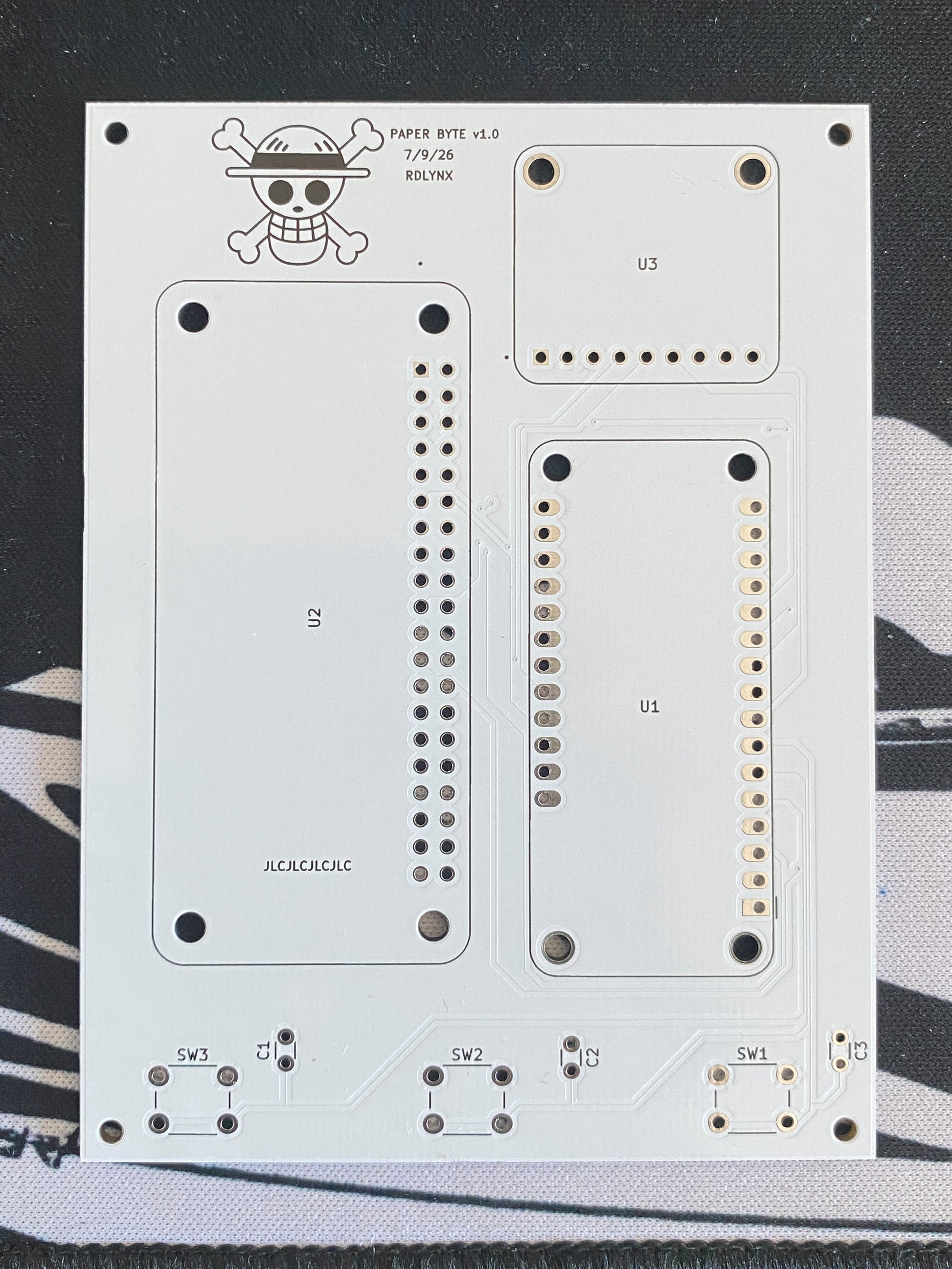
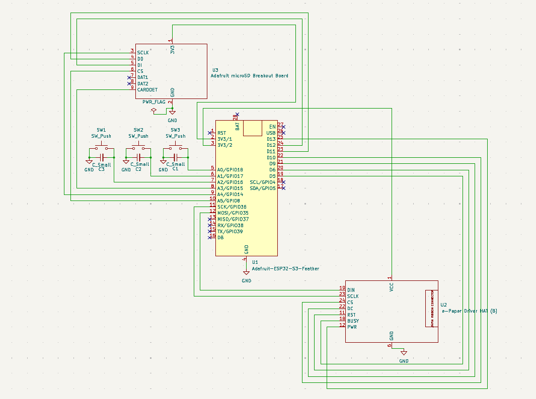
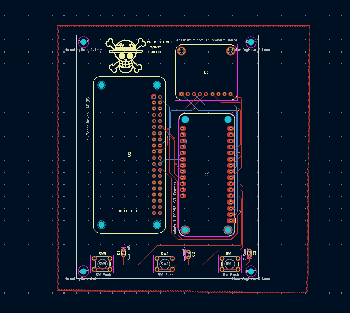
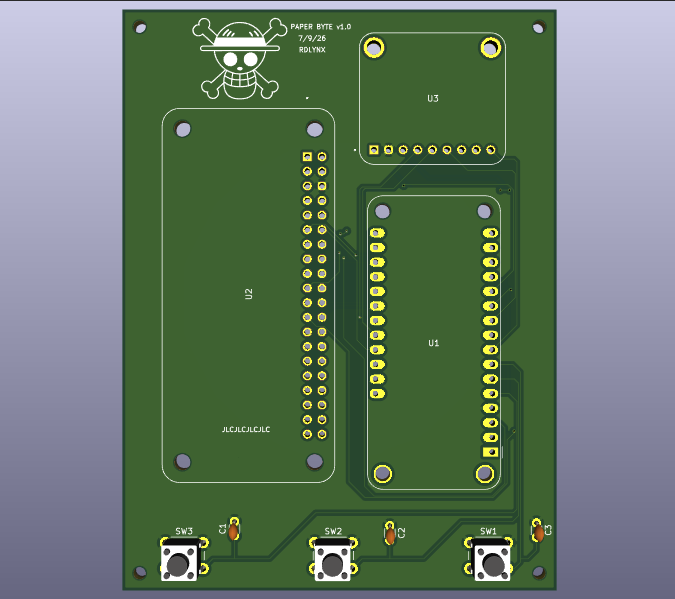
For my first PCB design, I wanted to keep things simple, so I used through-hole footprints for every component, easy to hand-solder and forgiving of small layout mistakes.
I kept the board down to three components: the ESP32-S3 Feather, the SD card module, and the E-Paper Driver HAT.
The ESP32-S3’s power pins fed the other two components, and SPI handled all communication — the SD card module and the driver HAT each run on their own dedicated SPI bus.
For the next version, I’d like to switch to SMD components and hand-lay out everything myself, so all the routing between components lives on a single PCB rather than being split across separate boards.
Software Design
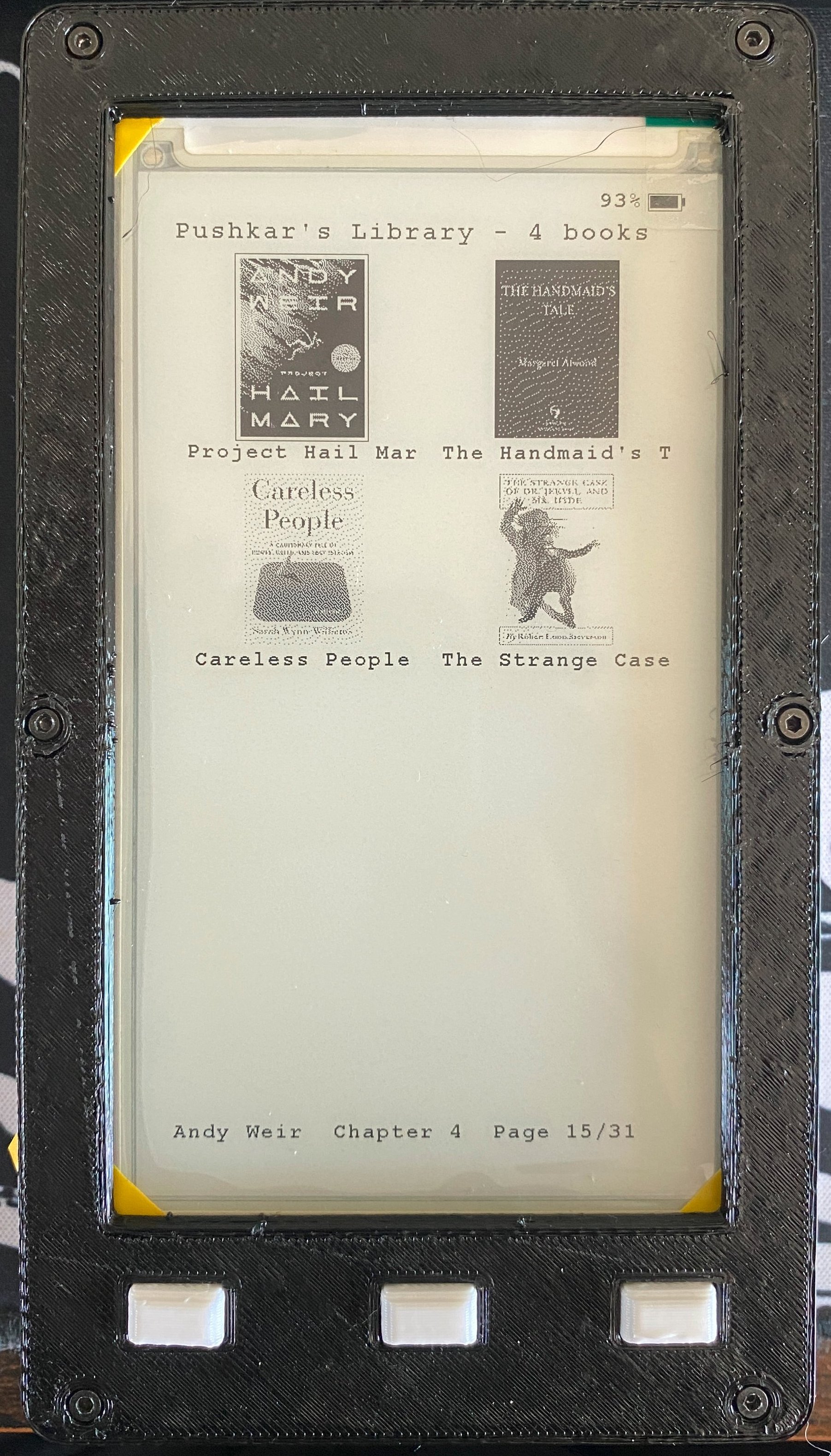
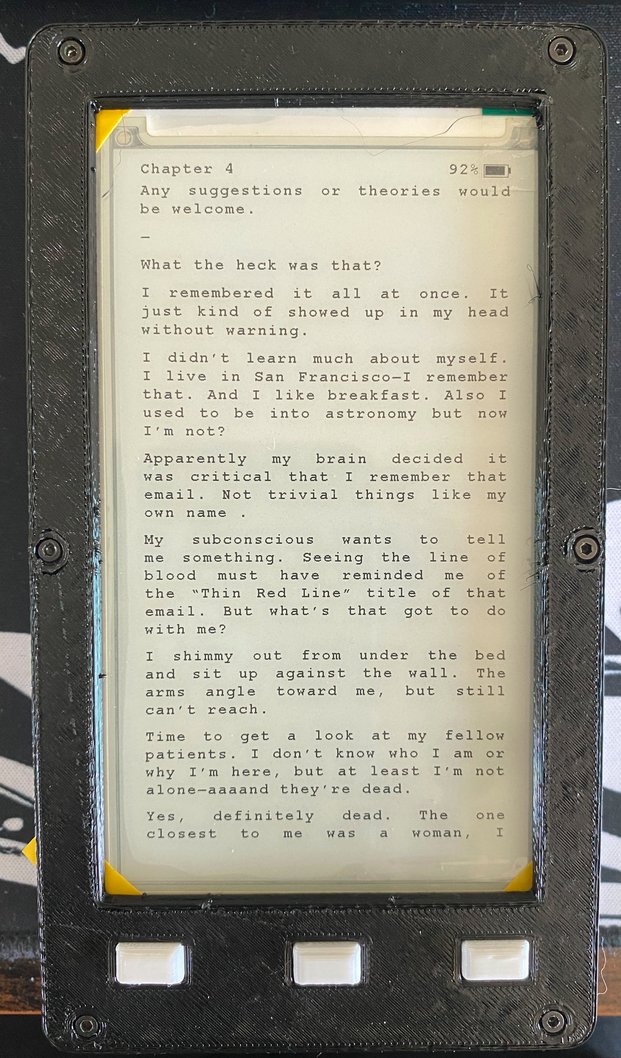
The firmware runs on the ESP32-S3 as a single state machine with six screens — Library, Reader, Menu, Settings, Table of Contents, and Wi-Fi File Transfer — driven by the three buttons. Underneath that, it’s a straight pipeline: EPUBs are unzipped and parsed one chapter at a time, laid out into pages sized to the display, and rendered to the e-paper screen. Position, settings, and cover art are all cached to the SD card so the device reopens exactly where it left off.
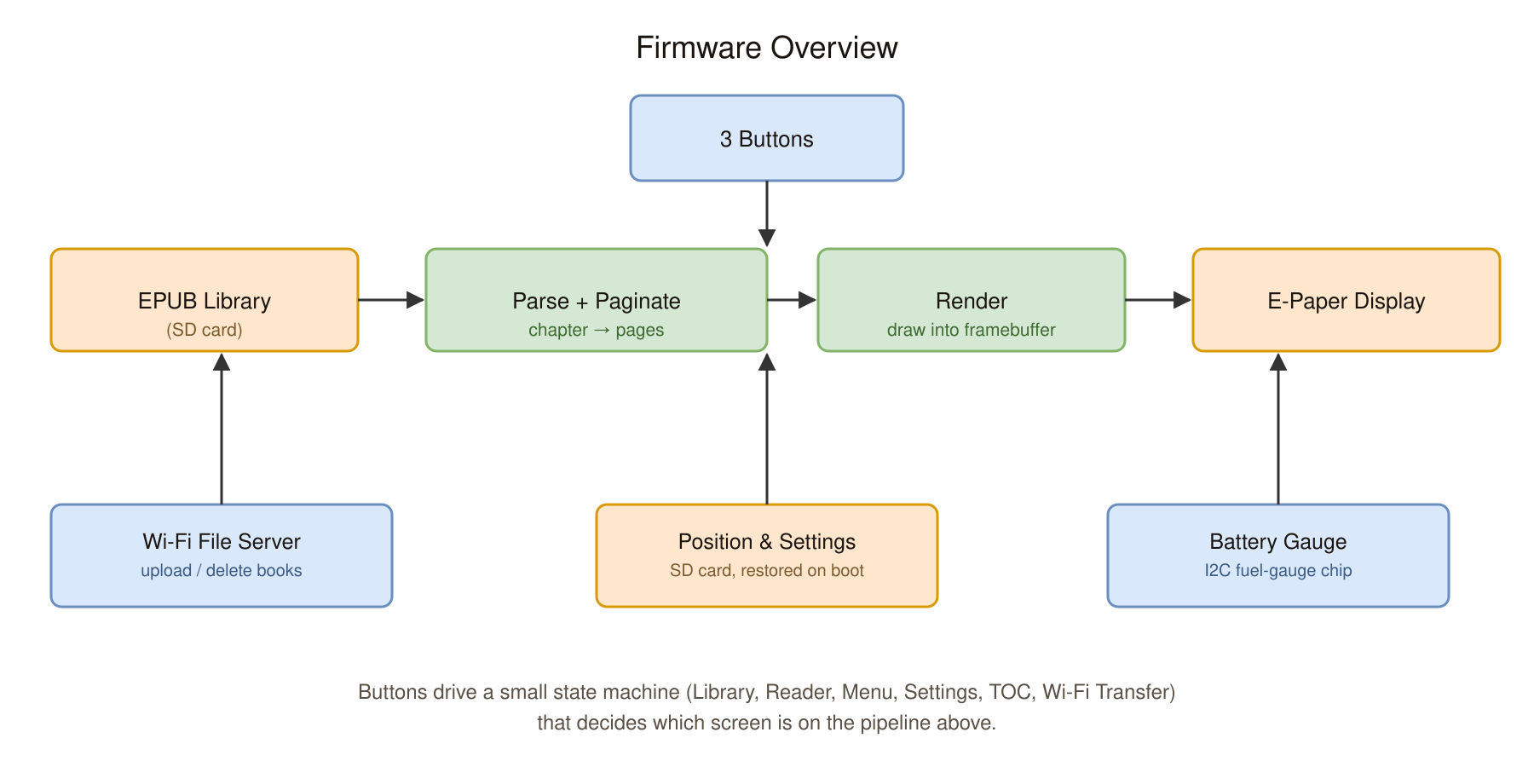
Each chapter is only parsed and laid out once, then kept in RAM, so flipping pages just re-renders from that cache and only crossing into a new chapter costs a re-parse. Sleep leans on the fact that e-ink is bistable — the screen holds the book’s cover at zero power, and waking up drops straight back into the reader.
Assembly and Design
The final design turned out much cleaner, with the PCB eliminating nearly all wiring. The only wires left were a USB-C cable exposing the ESP32’s charging port, the battery connection, and one small power jumper between the SD card module and the e-paper driver to patch a missed trace.
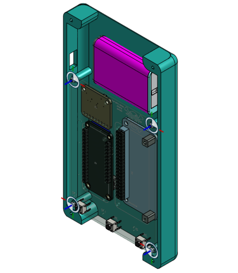
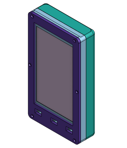
The final assembly with the 3D printed case looks something like this.
Acknowledgements
A lot of people helped me get this project done. It ate a lot of my weekends and evenings after work, but I’m really happy with how it turned out, and there’s still plenty I want to improve. Special thanks to Chris, Justin, and Carlos for helping with several of my questions, and to Ayesha for giving me her 3D printer, which has made prototyping and iterating on the mechanical design so much faster.